|
FIVE
SPEED CONVERSION
As the layout of the four and five speed gearboxes is the same, and the
shaft positions and overall lengths were unaltered, it is very viable to fit five speed
gear clusters into engines that were originally built with four speed gearboxes. If
possible, the fiting of the 1973 cluster is preferable to the 1972 cluster. The earlier
cluster had a number of weak points and these were all addressed for 1973. Also, there are
many variations to the sleeve gear early in the five speed productions and it is best to
avoid these variations. The earlier cluster can be updated, but the cost is quite high.
All the twins used the same components and the clusters from a twin can be fitted, with
only the Trident mainshaft being required in addition.
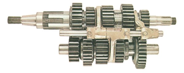
An early Quaife 5-speed gear cluster
There are two main modifications to make to a four speed gearbox casing to
allow the fitting of a five speed gearbox.
Firstly, the shield wall of the main casing, behind the sprocket main
bearing, must be opened up to 1-11/16", or slightly more. This is to allow the sleeve
gear (also called the high gear) to fit the new roller bearing correctly. It is also worth
checking that there will not be any foul between the outer face ends of the sleeve gear
teeth and the case when the gear is in position. It is just possible that the shield wall
will have to be thinned. I have had to do this twice in about 50 fitting operations
carried out over the past 10 years.
Secondly, the shield wall behind the mainshaft bearing in the inner cover
needs opening to 1-1/8". This is to allow the nose of the combined mainshaft first
and second gear to abut the bearing. It is this gear, and the arrangement of the kickstart
ratchet that positions the mainshaft. It is permissible to remove all the kickstart
equipment and replace it with a spacer of sufficient length to ensure that the tightened
nut at this end of the mainshaft locates it firmly against the inner gearbox cover
bearing, if the kickstart is not required.
Two types of five speed camplate were produced by Triumph. These are fully
interchangeable in service. The earlier one is "fully round" and must be fitted
before the sleeve gear. The later type, the "low inertia" camplate, has excess
material removed from the periphery and had "ears" at the end of the index
plunger track. One of these ears was used in the T-160 Trident to operate the neutral
switch. If an "eared" camplate is being fitted to an earlier Trident or Rocket
III crankcase, a small notch will have to be cut in the inner edge of the inner cover
joint of the main crankcase to allow the camplete to fully rotate. The later camplate also
has the advantage of being able to be fitted and removed with the sleeve gear in position.
It is always advantageous to use the latest T160 type of index plunger,
plunger housing, and spring. The plunger and plunger housing are the longest types
produced, and the plunger has a rounded nose. This assembly gives the sweetest action to
the selector mechanism. The T140 type items were slightly different in design, although
useable.
It is obvious that the gearbox inner quadrant (sometimes called the
butterfly quadrant) needs changng for a five speed component, but changes that are
required for the footchange quadrant and plungers are often overlooked. In a five speed
arrangement both the footchange quadrant and plungers are modified from their four speed
predecessors and failure to use these components will result in over selection. The five
speed footchange quadrant can be visually identified by having extra material left on it,
compared to the four speed item, in way of the positive stop. This is because of the
reduced travel between each gear in the five speed selection arrangements. The five speed
footchange plunger has a larger cutout than its four speed counterpart The top edge of the
pawl is much nearer to the diameter of the plunger than in the four speed component where
the top edge of the pawl is closer to the circumference of the plunger.
The footchange spindle is carried over from the four speed arrangements,
and is just pushed from the footchange quadrant. It is convenient that the T140 (LH)
footchange component has all the correct dimensions for fitting to Tl50 and Rocket III
footchange shafts. Beware, the T160 footchange quadrant is not suitable, as the hole for
the shaft is too small.
The selector fork spindle must be the correct one for the crankcases.
Earlier spindles had a reduced diameter end that fitted into the case near the output
bearing. Later four and five speed models had this step deleted, and the through-hole on
the case was made blind. There is a flat on the later spindle to allow air or oil trapped
in the blind hole to escape when fitting the later spindle.
The following set of instructions are not meant to dismay, but need to be
read and understood...
INSTRUCTIONS
AND SUGGESTIONS FOR FITTING THE FIXED GEARS TO A TRIUMPH 5-SPEED LAYSHAFT
If the layshaft is complete, the fitter may find that all the following is
superfluous, however, if a gear is changed, be prepared to check! These instructions apply
to the late layshaft assembly only. Eadier ones have a different design, which will be
obvious on inspection.
When fitttng the fixed (top) gear and spinning (fourth) gear to the
layshaft, it is possible that various machining operations will have to be carried out, to
ensure correct positioning of the gears on the shaft, and the shaft in the gearbox.
In a Triumph gearbox the length of the layshaft assembly between the outer
face of the first gear driving dog and the outer face of the top gear pinion must be such
that a small amount of end float exists between the thrust washers, when the inner cover
is in position. From experience, it seems a good rule of thumb length is 4.907", but
this may vary for any particular gearbox shell.
The layshaft is located by the circlip in the top gear pinion and the
circlip situated between the first gear pinion and the driving dog.
The first stop in the assembly is a "dummy run". With the top
gear pinion circlip fitted and the spinning gear fitted to the layshaft, carefully push
the top gear on to the splines, until the circlip abuts the end of the splines. Be careful
not to push too far or too hard, as it is very easy to broach the circlip with the
splines. Fit the first gear dog circlip and dog and measure the overall length. This will
then allow calculation of the amount the layshaft has to be "shortened". This
material may not all have to come from the layshaft itself because a clearance has to be
maintained between layshaft fourth and layshaft top. Fifteen thousandths (0.015")
seems to be a suitable figure.
The effective length of the shaft can be shortened in three ways,
depending on how the shaft has to move to adjust the clearance between top and fourth any
combination of the following can be used:
- Grinding the end of the spline that the top gear abuts will close the
clearance between top and fourth gears and shorten the layshaft by moving it further in to
the top gear.
- Surface grinding the outside face of the top gear will shorten the
layshaft assembly without affecting the clearance between top and fourth gears.
- Surface grinning the inside face of the top gear will increase the
clearance between top and fourth gears without affecting the layshaft assembly length.
Ideally, if this operation is being carried out, and the gearbox in which
the gears are to be fitted is available, it is very worthwhile to make a further check
before deciding where to modify the above components.
When the layshaft is in the gearbox, and first gear is selected, the gear
itself moves into engagement with the driving dog. The layshaft should also be positioned
so that the first gear does not contact the circlip, which is positioned between first and
the driving dog. A measurement taken between the circlip and the first gear during the
"dummy" assembly will allow accurate decisions to be made as to where and how to
modify the layshaft and top gear to obtain the perfect fit.
Submitted by: Phil Pick
Comments or Suggestions? 
© All Content Copyright 1997-2026 Triples Online. All rights reserved.
|