|
Indicators are ok - even if they do detract from the
classic lines of the bike . . .
- but if they are going to be added to a bike why not do
it properly and have a four-way hazard warning circuit?
Here is an upgrade to the existing indicator circuit to provide hazard
warning lights. Again, in keeping with our over-riding priority, there will
be no permanent changes to the existing look or components of a stock bike.
Obviously, this information only applies to those bikes that were originally
shipped with indicators.
Note: these directions are quite lengthy -
to be as helpful as possible. For a quick overview first take a look at the
wiring diagram and the photos.
Overview
1
The required components are shown below, along with suggested sources. We will
take the electrical feed from the zener-diode (which is already fused but not
controlled by the ignition switch).
a) Fuse Holder (Radio Shack /Tandy : ) - optional,
to provide additional protection
b) Toggle Switch (Radio Shack / Tandy : 275-653A) -
to switch headlights and the hazard lights
c) Flasher Unit (Wagner 12v)
- a car unit from any auto parts outlet (Kragen, Halfords etc)
d) Silicon Diodes (Radio Shack / Tandy : 276-1114) - used
to keep the original indicator circuits isolated
e) Quick Disconnects (Radio Shack / Tandy : 64-3134) -
spade terminals for the wiring
You'll also need some wire, preferably colour-coded to match the existing
circuits. You can get it (in order of decreasing cost) from:
- a British Bike electrical supplier
- an electrical supply outlet
- strip it out of an old car in a scrap yard (the Datsun 240z/260z/280z
is a good source)
- an old wiring loom from another bike
|
|
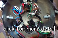
2
Everything we do in this example will take place inside the front
headlight shell and attached to the front indicator connectors - this
means that to make this upgrade to an earlier bike with the flat 'pancake'
style headlight shell will be difficult as there is very little room. It is suggested that
these earlier bikes have the upgrade fitted under the seat and attached to the
rear indicator connectors - you will have to find an alternative method of
mounting the components and securing a source of power.
Open the headlight shell and make sure you have enough room behind the
headlight unit - if you have converted your headlight to a car style 3
prong connector it may be a tight fit. We are going to replace the existing headlight on/off
switch (99-0563) at the top of the headlight shell
because we need to add a double pole, double throw (DPDT) switch to work
both the headlight and the hazard lights.
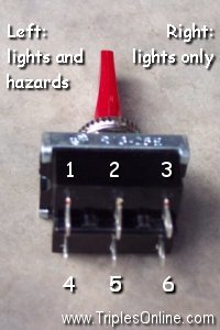
We want our hazard lights to work in the following conditions:
- when the ignition is ON
- when the ignition and lights are ON
- when everything (ignition, lights, etc) is OFF
The suggested toggle switch (shown left) works very well for our application:
- the center position is OFF
- to the right (when facing in the direction of the
bike) will be our normal headlight ON
position (on the T160 the ignition switch would also need to be set to headlights)
- to the left will be our hazard light ON
position. This position will also work the headlights - so we can have
headlights and hazard lights. We will also wire it such that the hazard circuit will
be 'live' or
'hot' when the bike is parked without the key. This is, perhaps, a
personal preference - but don't be alarmed - any blue/brown circuit on
your bike is always in this 'live' state (all bikes have this feed to the
zener-diode under the headlamp and the T160 has an additional accessory
connector under the seat).
This toggle switch is also rather handy because it has a red toggle (in
the exact style of the original) - the only visible indication of our
upgrade.
|
| |
 |
| 3
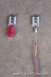
A word on the connections we use. The typical spade connectors found on
the Triples are 0.25". The new toggle switch comes with smaller
terminals so we will have to use some 0.187" female connectors to
attach our wiring - alternatively you can solder the wires directly to the
switch.
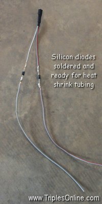
We use bare connectors (after stripping the existing and garish blue or
red sheathing). We assemble the components by crimping and then soldering
for added security. We then cover them with black, heat-shrink tubing to
provide insulation and a neat professional appearance.
|
|
|
| 4
The circuit is pretty simple. We take power from the zener-diode under the
headlamp shell. We pass this through the (optional) fuse holder, on to the
flasher unit, and from there to the toggle switch. We now have a
fuse-protected flasher and switch and need to connect into the indicator
circuits. We obviously need to attach our new circuit to both indicators -
however, while a direct connection would work for the hazard flashers it
would also turn our original handlebar indicator switch into a hazard
warning switch! We need a way to make our hazard circuit a one-way circuit
for the flow of the current. Hence the use of the two diodes.
|
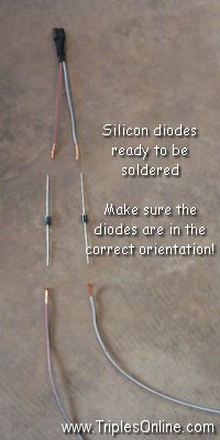 |
5
If we add a diode to each branch of the circuit as it leaves the toggle
switch but before each wire goes into the respective front indicator
bullet connector we will have isolated each circuit. See the wiring
diagram and the photos.
NOTE: the two diodes MUST be in the correct orientation - test before soldering!
|
 |
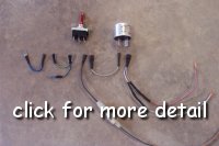
Installation
|
6
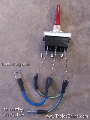
First, we'll take care of installing the existing headlight circuit. Make
up the wiring, shown right. Connect the blue input feed to the central
terminal 2. Then connect the blue/yellow output wire to terminals 1 and 3
- this will allow the headlight to work with or without the hazard lights.
|
|
 7
For the hazard circuit attach one end of the fused brown/blue feed to the
flasher unit and feed the other end out of the headlight shell via one of
the large black grommets. Attach it to the other brown/blue wire on the
zener-diode. 7
For the hazard circuit attach one end of the fused brown/blue feed to the
flasher unit and feed the other end out of the headlight shell via one of
the large black grommets. Attach it to the other brown/blue wire on the
zener-diode.
Attach the flasher unit to terminal 6 on the toggle switch and
attach the diode wiring to terminal 5.
|
| 8
Finally the two leads to the indicator connectors can be inserted. You
will notice that the 4-way bullet connectors for each indicator are
completely full (a wire goes to each of: the indicator switch, the front
indicator, the rear indicator, the warning bulb). Improvisation is called
for: don't add a connector to the end of the diode wires, simply leave
them bare. Then for each side, remove the front indicator bullet
connector from it's 4-way connector, insert the bare end of the respective
diode lead and then replace the front
indicator bullet. They will hold just as securely (if not more so) as the
red grounding wires in the headlamp shell.
|
<need pic of final wiring> |
 |
9 Voila!
Note that the original flasher unit and the hazard flasher unit might
be on at the same time. This is not a problem electrically or in
operation. The car-type flasher used in the hazard circuit will draw
more current when turned on and operate (ie open) long before the
reliable old Joe Lucas item. As it opens it will allow the Joe Lucas
item to start warming up (it takes a while) - but before the Joe Lucas item
gets up to a decent operating temperature to be able to open the
bi-metal strip in the car
flasher will have cooled down to close and therefore start the
process over again - the Lucas item will never begin to operate.
|
|
|
|
Comments or Suggestions? 
© All Content Copyright 1997-2026 Triples Online. All rights reserved.
|
|