10. PHYSICAL TESTING-EQUIPMENT
So much for the theory and the concepts - how do these thermostats work in practice?
I decided to construct a simple test rig to test the operation of these thermostats at different temperatures.
At the age of 13 I was in hospital undergoing surgery when three patients were brought into the hospital ward. They had been burned on the faces and hands when a pipe containing hot oil under pressure had burst when they were testing a large steam turbine. Having seen those burns and the skin flaking off showing raw flesh underneath I decided not to use hot oil!
By coincidence when thinking about how to do these tests, our domestic hot water kettle went wrong. As I am British this was of course classified as a major emergency as it is essential to have boiling water in order to make tea. While my wife was dispatched on the urgent task of buying a new hot water kettle I examined the failed kettle.
What had malfunctioned was the device to switch off the kettle as the water boiled. It was in fact switching off the kettle at a temperature well below boiling point. However the kettle was not leaking and the heating element was working OK.
So the idea germinated of immersing the thermostats in hot water in the kettle and once the temperature had stabilized to blow low pressure compressed air through the inlet pipe to the thermostat from the engine and to visually look to see where air bubbles came out of which connection.
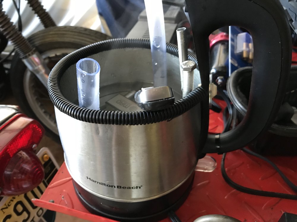
In order to do this the kettle had to be cut down so that the top opening was at its maximum diameter thus allowing the thermostats, complete with their connections, to be lowered into it.
The kettle was cut down, the top 1/2" was then folded over inside the kettle to avoid sharp edges at the top. There were still some sharp points remaining so a piece of split electrical plastic wiring conduit was cut and fitted around the top edge. The unit as modified is shown in Photo 7.

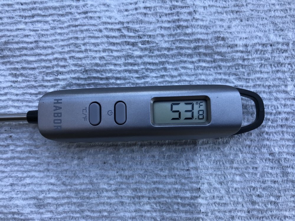
The next problem was how to measure the temperature of the water in the kettle. After thinking it through without success I decided to be modern and resorted to Google. There I came up with electronic meat thermometers. The unit which seemed to fit the bill well is a Habor Model #HBCP022AH.
The specifications for this unit claimed a temperature measurement range of -58ºF (-50ºC) to 572ºF (300ºC).
They also claimed an accuracy of plus or minus 2ºF (1ºC) between 32ºF (0ºC) and 212ºF (100ºC).
All this for $8 and free shipping! - so I ordered one. The unit is shown in Photo 8. It came and looked OK. I decided to check its accuracy as I found it difficult to believe the claims for accuracy for such a low price.
So - remembering my days as a heat transfer development engineer going back 50 years or so I decided to calibrate the thermometer at the two temperatures readily achieved in a domestic environment and which are reliably accurate. These are melting ice (32ºF/0ºC) and boiling water (212ºF/100ºC).

I first put the thermometer in melting ice, then removed it for a few minutes and put it into boiling water. I then removed it for a few minutes and put it back into melting ice. This was repeated for a total of three measurements at each temperature. In this way I also tested the thermometer for any hysteresis.
The results were as below (in ºF):
In melting ice: 34.0, 33.3, 32.9 Average 33.4
In boiling water: 213.6, 213.6, 212.5 Average 213.2
The results were within the accuracy claimed in the specifications and were in my view pretty impressive considering the price of the unit.
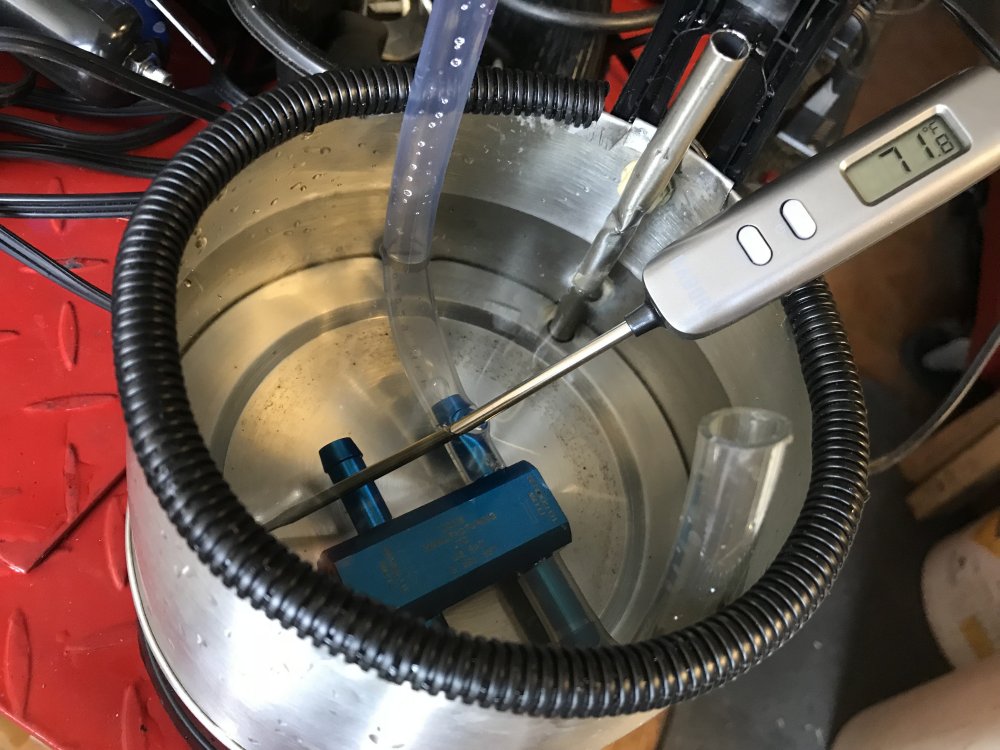
I then connected my air blast nozzle (used to blow out oil ways etc) to the outlet from a low pressure regulator connected to my workshop compressor. I then cut a length of transparent plastic tubing and connected one end to the thermostat connection "from engine". 1 could then use the air nozzle to blow air into the open end of the plastic tube with fine manual control on the air nozzle trigger and thus blow low pressure compressed air into the thermostat.
I then experimented with different air pressure with the thermostat in cold water in the hot water kettle. I settled on an air pressure of about 2 p.s.i.g. as a pressure which gave a steady flow of bubbles through the thermostat. Any higher air pressure and the whole body of water was full of bubbles obscuring any detailed observations of which connections the bubbles were coming from. Any lower air pressure and the bubble stream was not regular.
The total test set up is shown in Photo 9.

In initial testing I soon found out that the majority of the air just went straight through to the "to cooler" connection. This was because I was not simulating the resistance to flow of the cooler. So I fitted another length of transparent plastic tubing to that connection with the other end of the plastic tube above the top of the kettle. I could then largely cover the open end of that tube with a finger and thereby simulate the cooler resistance.