6. TC UNIT DETAILED DESIGN
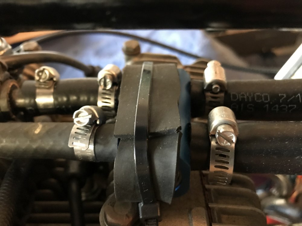
A TC unit installed on one of my triples is shown in Photo 3. In the installation the TC unit is wrapped in a piece of tire inner tube and is secured using a plastic tie.

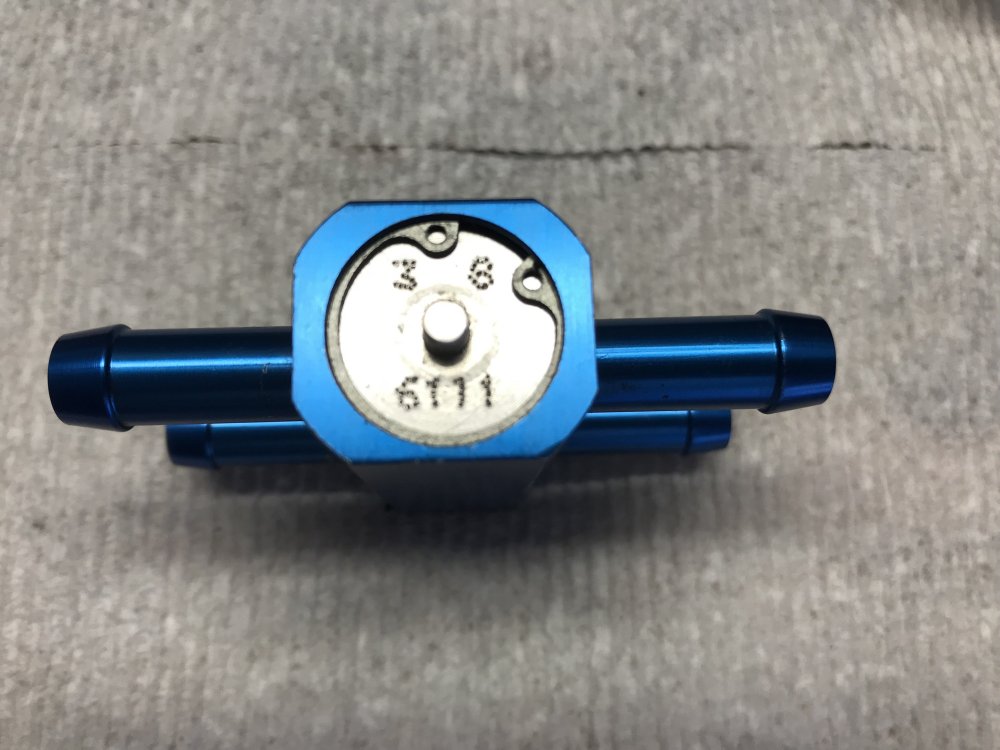
The unit itself is shown in photo 1 and has four connection pipes all of the same size in two pairs opposite each other.
The unit dimensions are as below:
- Length of body 2 3/8"
- Width or body 1"
- Depth of body 7/8"
- Connection length (total) 1"
- Connector shank diameter 0.379" measured (3/8" nominal)
- Connector barb diameter 0.426" measured (7/16" nominal)
The housing is marked for flow connections as "to cooler" and "to trans". Bearing in mind the origin of the unit as a transmission oil thermostat then the marking "to trans" on a triple means "to oil tank".
The oil connections are slightly smaller than the bikes cooler hoses but in practice the hoses clamp down on the shank of the connections and the barbs prevent the hoses sliding off.
The unit was disassembled. At one end is a circlip (see Photo 4).

With the circlip removed the inner parts can be removed from the housing.
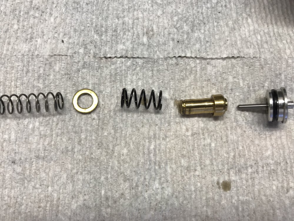
The internal componentry is shown in Photo 5.

At the right hand side of the photo is the end plug showing the "O" ring seal which seals into the housing bore.
Next is the metal shaft which goes into the wax capsule and then the wax capsule itself.
The bottom of the wax capsule is marked 8 C6.
The meaning of these markings is not known.
In the photo next to the wax capsule is the shuttle valve retaining spring.
Then the shuttle valve (a simple washer) and then the main return spring.
In the assembled condition the shuttle valve retaining spring goes over the body of the wax capsule and rests on the shoulder of the capsule. The shuttle valve then slips over the capsule body, compressing the shuttle valve retaining spring. Note that the shuttle valve I.D. is a good sliding fit on the wax capsule outer body.
The main return spring is fitted with its end coil located in the groove close to the end of the wax capsule.
In assembly the wax capsule metal shaft is placed in the recess in the face of the end plug and the assembly is pushed into the body housing and the circlip fitted to locale the end plug in the housing against the force exerted by the main return spring.
The assembled unit is shown in Diagram B.